Home > Automotive Water Pipe Blow Mold Manufacturing Service
Automotive Water Pipe Blow Molding Mold Manufacturing Service
Model: BL2505160 | Die Ref: F5120S
Booling custom‑designs blow molds for automotive water fill tubes, fully compliant with IATF 16949 quality standards. Every mold runs a complete trial on our in‑house EBM (Extrusion Blow Molding) machines before it ships, and we’ve validated a service life of 300,000 shots. We’re a trusted partner to Tier 1 cooling system suppliers for commercial vehicles worldwide.
- ISO 9001:2015 Certified
- Automotive-grade production compliance (IATF 16949 aligned)
- DFM + Moldflow Included — CMM Report with Every Mold
- 10+ Years Manufacturing
- 12-Month Warranty
- 24h Response
- Taizhou City (Mold Town)
Design and Manufacturing Key Points for Water Pipe Blow Molds
When we receive customer drawings, the first step is to confirm what fluid will be transported in the pipe and the long-term operating temperature range. Based on this, we select the proper material.
We do not randomly choose materials just to reduce cost. If the material selection is not correct at the beginning, issues such as cracking at quick-connect joints may occur after repeated thermal cycling during mass production, leading to rework and failure.
We ensure material matching from the start so that dimensional tolerances at sealing areas remain stable, and both high- and low-pressure airtightness tests can pass in a single validation.
For every blow mold we design and manufacture, including cavity inserts, pinch-off geometry, conformal cooling channels, and parison systems—we complete full trial runs before shipment.
Customer Testimonial
The BL2505160 mold delivered exceptional cycle time reduction — 43 seconds vs. our previous 68-second benchmark. T1 samples passed on first try with all 12 dimensional checkpoints within tolerance.
—— John Doe
3D Design Drawing of Automotive Water Pipe
UNIQUE PER CASE — Drawing package provided per project. Contact sales for your DFM & CAD package.

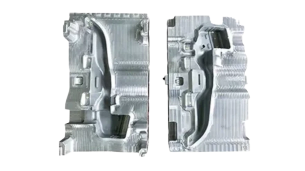
Automotive Water Pipe Blow Molds
Cavity half molds
Pinch-off inserts and core with cooling channels
Blow pin systems and parison control system
Suitable for PP, PA66, PA12, HDPE blow molding tools
Mold Engineering Case
The cooperation case is with a commercial vehicle cooling system division in Asia. The mold was used in a mass production line for vehicle cooling pipelines.
Issues with the original mold
- No DFM simulation during early design stage, causing warpage around the parting line and repeated trial adjustments.
- Unstable delivery schedule, often missing customer launch timing.
- Large dimensional variation during long-term production, sealing tolerance out of spec, resulting in leakage and deformation issues.
- Insufficient wear resistance, unable to reach 300,000-cycle service life requirement.
Improvements after optimization
- DFM analysis + blow molding flow simulation introduced early, eliminating parting line warpage and saving two rounds of trial corrections.
- Delivered in 40 days as scheduled, fully aligned with product launch timing.
- Stable mass production over 8 months, sealing dimensions controlled within ±0.05 mm, no batch leakage or warpage issues.
- Mold reached over 300,000 cycles of service life.
Based on stable performance, the customer placed additional orders for multiple variants of complex curved expansion tank and filling pipe molds, fully recognizing our capability in design, quality control, and delivery response.
+
From ~60% baseline → 30% improvement
+
From ~60% baseline → 30% improvement
+
From ~60% baseline → 30% improvement
+
From ~60% baseline → 30% improvement
Engineering Verification & Mass Production Performance
All molds undergo full-process validation on our in-house EBM (Extrusion Blow Molding) machines before shipment.
Inspection items include:
- Multi-point wall thickness scanning (CMM coordinate measuring machine inspection).
- Thermal cycle durability stability test.
- Sealing pressure decay air tightness test.
- Continuous trial molding stability verification.
Actual Mass Production Data:
- Sealing end dimensions consistently controlled within ±0.05mm tolerance.
- Zero mass leakage defects over 8 consecutive months of production.
- Mold service life exceeds 300,000 molding cycles.
- T1 first trial molding rework rate reduced by over 50%.


T1 Qualification — All Checkpoints Passed
- Custom-designed pipe geometry based on customer requirements, not modified standard mold bases.
- Cutting edge tolerance controlled within ±0.5mm for clean flash separation.
- Parting line follows the pipe centerline to prevent uneven wall thickness and deviation.
- Independent cooling channels for sealing cores, covering hard-to-cool areas.
- In-house trial molding ensures delivery of functional molded samples, not just molds.
Mold Types
For tubes of different structures, mold clamping method, cavity depth, pinch-off profile, core cooling structure and blow pin diameter require independent customized adjustment; a universal design solution cannot be applied.
Radiator Coolant Inlet Blow Molds
Short cavity depth with thick tube wall, expanded tube end designed to fit radiator caps. The core manufacturing difficulty lies in the mating sealing surface for radiator caps, which requires ±0.05mm tolerance for O-ring assembly.
The expanded tube end suffers the heaviest wear, so we adopt replaceable H13 inserts for easy later maintenance. For 30% glass fiber reinforced PP material, mold operating temperature is controlled between 60–70°C.
Expansion Tank Filler Tube Blow Molds
Long cavity with multiple bent sections and thin tube walls. The core manufacturing challenge is precise dimensional control of bent cavity sections. During molding, extra material is reserved to thicken bent zones with heavy blow stretching, while straight sections are thinned moderately to save raw materials. Improper parting line processing easily causes uneven wall thickness and finished part deformation.
Windshield Washer Fluid Filler Tube Blow Molds
Low thermal stress and generally low project budget; visible surfaces of finished parts are mostly located on vehicle front fascia. HDPE runs stably at standard mold temperatures with P20 mold steel. High-gloss polishing is required for visible cavity surfaces, with simple hose barbs at tube ends. Multi-cavity designs are widely adopted for this mold type to reduce unit production costs.
Mold Material Selection
Mold Steel Selection Guide
| Parameter | Value / Description |
|---|---|
| P20 | For PP & HDPE non-glass filled resin; Cost-effective standard cavity steel, stable dimension up to 500,000 molding cycles. |
| H13 | Heat-treated high wear-resistant steel, specially applied to pinch-off & sealing flare inserts for glass fiber reinforced PP/PA66 resin. |
| S136 | Corrosion-resistant stainless steel, prevents ethylene glycol coolant residual etching, can be mirror polished for high appearance visible pipe surfaces. |
| 2344 | High-performance premium tool steel with superior toughness & polishing performance; For high-volume production (1,000,000–2,000,000 cycles) with tight sealing tolerance PA66 cooling pipes. |
| Application | Plastic resin | mold steel | Mold Surface Temperature (°C) | Practical Test Advantages |
|---|---|---|---|---|
| Radiator Inlet Pipe | PP | P20 / S136 | 60–70 | S136 resists ethylene glycol corrosion; H13 inserts deliver superior wear resistance |
| Expansion Tank Matching Pipeline | PP | P20 / H13 | 50–60 | Main cavity P20 controls cost; H13 inserts on high-wear areas extend service life |
| Windshield Washer Fluid Inlet Pipe | HDPE | P20 | 20–30°C | High-gloss polishing, high cost performance, stable dimension within 500,000 molding cycles |
| Parameter | Value / Description |
|---|---|
| Sample #1 | Row 1, Content 1 |
| Sample #2 | Row 2, Content 1 |
| Sample #3 | Row 3, Content 1 |
IATF 16949 Quality System Implementation
Our factory fully implements the IATF 16949 automotive quality management system across all processes. Every project is standardized to meet OEM audit requirements.
Complete quality control documentation includes:
- Project initiation stage
We provide full APQP documentation covering all five phases. FMEA for both tooling and molding processes is developed and delivered together with the mold. Customers can access all documents at any time. - Raw material control
All mold steels for cores and inserts come with original mill material certificates and spectrographic analysis reports. Batch sampling and traceability records are maintained for every shipment. - Dimensional accuracy control
Pipe tolerances are controlled within ±0.05 mm. We implement MSA (Measurement System Analysis) to ensure all inspection data is reliable, consistent, and traceable. - Mold delivery and production release
At final mold acceptance and shipment, we provide complete PPAP (Production Part Approval Process) documentation, fully compliant with OEM requirements for both domestic and international automotive manufacturers.
| Temperature Settings (°C) | |
|---|---|
| Sample #1 | Sample #1 |
| Sample #2 | Sample #2 |
| Sample #2 | Sample #2 |
| Sample #2 | Sample #2 |
| Temperature Settings (°C) | |
|---|---|
| Sample #1 | Sample #1 |
| Sample #2 | Sample #2 |
| Sample #2 | Sample #2 |
| Sample #2 | Sample #2 |
| Temperature Settings (°C) | |
|---|---|
| Sample #1 | Sample #1 |
| Sample #2 | Sample #2 |
| Sample #2 | Sample #2 |
| Sample #2 | Sample #2 |


Mold Section Key Parameters
| Parameter | Value / Description |
|---|---|
| Pinch-off edge width | 0.3–0.5mm, used to control flash cutting quality and sealing stability. |
| Parting line | Located along tube centerline, controlled within ±0.5mm deviation. |
| Core cooling | Independent cooling channel at sealing end to improve local cooling efficiency. |
| Blow pin | Blow pin matched with nozzle within ±0.02mm to ensure consistent sealing during forming. |
Mold configuration
Our manufactured water pipe blow molding molds.
| Stage | Work Description | Typical Duration | Deliverables |
|---|---|---|---|
| DFM Review | Evaluate manufacturability including geometry, wall thickness distribution, sealing tolerances, and overall molding risk | 2–3 days | DFM report + preliminary mold concept |
| Mold Design | Cavity layout design, parting line strategy for bent tube, cooling system design, pinch-off structure design, blow pin sizing, and mold base selection | 1–2 weeks | 2D engineering drawings + 3D mold assembly model |
| CNC Machining | 5-axis CNC machining of cavity and core inserts, including roughing and finishing operations | 1–2 weeks | Machined inserts ready for EDM finishing |
| EDM Finishing | EDM machining of pinch-off features, undercut detailing, surface texturing, and polishing of functional surfaces | 3–5 days | Finished inserts meeting required tolerances |
| Mold Assembly | Assemble inserts into mold base, connect cooling channels, install guiding system, and adjust blow pin mechanism | 3–5 days | Fully assembled mold ready for trial molding |
| Trial Molding | Run mold on EBM machine, adjust parison settings, produce first samples, measure wall thickness, and perform pressure tests | 1–2 days | Qualified samples + validated mold performance |
Technical Drawings & 3D Models
UNIQUE PER CASE — Drawing package provided per project. Contact sales for your DFM & CAD package.
After-sales Service
We provide full lifecycle support for blow molding tooling:
- On-site parameter tuning during initial production
- 7×12 technical remote support
- Mold refurbishment and optimization services
- Spare H13 inserts available for fast replacement (48-hour dispatch)
- Lifetime technical consulting for new projects and material changes
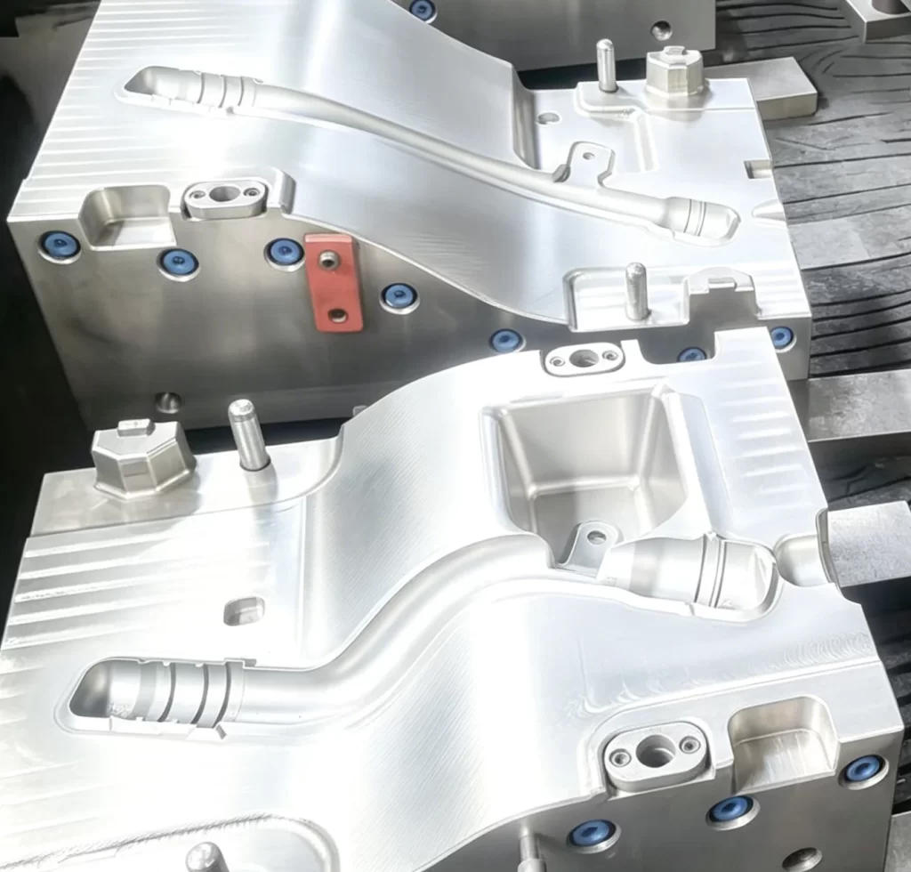
Mold Design Highlights
Our water inlet blow molding molds rely on four core precision points: pinch-off area, parting line, dedicated cooling channels, and precision blow pin.
Pinch-off Edge Design
Internal Mold Structure: Pinch-offs, Parting Lines, Cooling Systems, Blow Pins
The pinch-off is the critical structure for trimming parison flash. The cutting edge of the pinch-off is machined to 0.3–0.5mm width with a matching 15–20° mating bevel. For glass fiber reinforced PP molding, edge width is slightly increased with H13 inserts. An overly narrow edge delivers clean flash removal but leaves cutting marks on tube bodies; an excessively wide edge fails to fully trim flash and requires manual burr removal.
Parting line Design
The parting line is the most critical feature of coolant filler tube molds. The parting line is arranged along the tube central axis instead of simply following the theoretical center of CAD models, as plastic shrinkage during mass production leads to actual center offset.
Example: For a 600mm expansion tank tube with three bends, the parting line of each cross-section must be controlled within ±0.5mm of the tube center; otherwise, uneven wall thickness and finished part warpage will occur.
Cooling system
Cooling channels are prioritized at sealing ends with 3–4mm wall thickness. If tube bodies and sealing ends are cooled simultaneously, thick-wall zones dissipate heat slowly with large shrinkage, causing tube bending deformation. Water spray nozzles with independent cooling circuits are installed inside sealing end cores. For cavity areas unreachable by standard drilling, conformal cooling channels are laid along the cavity contour.
Blow pin
The fit clearance between blow pin and tube port is controlled within ±0.02mm. An undersized blow pin causes air leakage from the tube port and incomplete parison inflation; an oversized blow pin stretches the tube port during assembly and damages sealing dimensional accuracy.
Transparent Standardized Service Process
Requirement Intake
We take your product 3D drawings, annual production volume, EBM machine tonnage, sealing tolerances, and resin grade. Then we run a DFM analysis and initial mold‑flow simulation free of charge, and send you a preliminary report.
Itemized Quote
Based on steel grade, number of cavities, simulation scope, inspection criteria, and trial‑run hours, we give you a complete cost breakdown. You’ll see exactly what you’re paying for—no lump‑sum guesswork.
Design & Simulation
We complete the full mold structure and blow‑cooling simulation. The simulation files and DFM report are sent for your sign‑off before we order any steel.
Machining & Manufacturing
During production, we push regular updates: machining progress, spectro reports on the actual steel used, and real‑time CNC videos so you can see the work as it happens.
Trial molding & Acceptance
At T1, we provide CMM inspection reports, production‑representative samples, and wall‑thickness distribution maps. You can join the trial on‑site or remotely—whatever works for you.
Packaging & Shipping
All PPAP documents, material certificates, full inspection records, and the mold warranty package are shipped together with the tool.
After‑sales & Support
We cover the mold for the agreed shot‑count warranty period. Beyond that, you get lifetime free technical consultation, plus insert refurbishment and expedited spare‑part service whenever you need it.
Frequently Asked Questions
UNIQUE PER CASE — Drawing package provided per project. Contact sales for your DFM & CAD package.
How is thick sealing area cooling handled in water pipe molds?
Cooling channels or baffle systems are added directly into the core to bring coolant closer to thick sections. For complex geometries, conformal cooling is applied.
What is the typical lead time?
- Single cavity radiator filling neck mold: 5–6 weeks
- Washer pipe multi-cavity mold: 4–5 weeks
- Complex molds with side actions or conformal cooling: 7–8 weeks
Send us your pipe 3D drawing and plastic resin grade
Please inform us annual output, EBM machine tonnage and sealing tolerance requirement. We will send you full mold solution, steel grade recommendation, parison profile plan and trial molding schedule.
- Request a Free Quote
Respond within 24 hours · No spam · NDA available
By submitting, you agree to our privacy policy. We never share your data.
- Free DFM review with every inquire
- NDA available upon request
- No obligation — just a conversation
- Expert engineer assigned to your project