
Home > IBC Blow Molding Mold Manufacturing
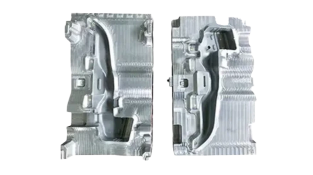
IBC Blow Molding Mold Manufacturing
Model: BL2505160 | Die Ref: F5120S
Our industrial-grade IBC tote molds are fully optimized for even parison distribution, maximum batch yield and extended mold service life, substantially boosting finished product rates during continuous mass production. Crafted by Booling, they safeguard your packaging production lines and supply chain reliability to automotive OEM-grade standards.
- ISO 9001:2015 Certified
- IBC Tanks, Drums, Water Tanks & Industrial Containers — 1L to 3000L
- DFM + Moldflow Included — CMM Report with Every Mold

- 10+ Years Manufacturing
- 12-Month Warranty
- 24h Response
Video of IBC Blow Mold Trial Run
IBC Tank Mold Case Study
Booling recently delivered a 1000L IBC blow mold set to a chemical distributor in Southeast Asia. The client’s requirements appeared straightforward: compliance with UN 31HA1 standards, full 48-point 3D wall thickness scanning, and compatibility with their existing Haitian blow molding machine equipped with a 40L accumulator head.
Their previous mold set—purchased from a low-cost supplier—had been steadily eroding their margins. The scrap rate remained around 9%. The root cause was located in the pinch-off area: unstable weld seams, flash requiring two operators for manual trimming, and inconsistent wall thickness that forced overpacking of HDPE to ensure the minimum wall requirement was met. Each container consumed more resin, longer cycle time, and additional labor. After eight months of production, they found that the additional cost from scrap and rework of the “lower-cost” mold exceeded the initial price difference within just three months.


Before machining, we ran Moldflow analysis on the client’s part geometry. The simulation revealed two critical issues that were not addressed in the previous mold design. First, parison sag behavior—calibrated based on our die head geometry—indicated that a 14.7 kg HDPE parison at 195°C would cause excessive sag, resulting in wall thickness thinning down to 2.12 mm at the upper neck transition area unless compensated by PWDS (Parison Wall Distribution System) programming. Second, the geometry of the pinch-off inserts created a differential shrinkage zone at the interface between the sidewall and weld line, showing 1.7%–2.1% higher shrinkage compared to adjacent regions. This effectively introduced a persistent stress concentration zone in the most fatigue-critical area of the chemical container.
We reworked the pinch-off inserts twice. The first T1 trial showed a 2.3% deviation at the corner area and was rejected. After adjusting the PWDS curve and rebalancing cooling in the transition zone, the second iteration achieved ±0.32 mm wall thickness uniformity across a full 240-point CMM scan, with pinch-off deviation controlled within 1.7% of nominal.
On a DMG MORI DMU 80 P duoBLOCK 5-axis machining center—with positioning accuracy of ±3 μm and a working envelope of 800 × 650 × 550 mm—the pinch-off insert cavities were re-machined. The full profile accuracy was maintained within ±3 μm.
The mold is now in mass production, manufacturing HDPE IBC tanks for a hydrofluoric acid supply chain. The customer’s scrap rate decreased from 9% to below 2%, while batch yield improved from 91% to 98%.


Customer Testimonial
We relied on a competitor’s IBC molds for 8 months, with constant scrap losses eating into our profits. Booling reworked the cooling circuits and fitted integrated automatic deflashing, lifting our production yield from 91% to 98%. The molds have clocked 140,000 cycles and are still running reliably.
—— Production Manager, Middle Eastern Petrochemical Processor
Many manufacturers rush IBC mold development to a 25-day turnaround to cut lead times, yet this often requires compromises in structural design, cooling systems and wall thickness control. These defects rarely surface during initial trial molding but emerge gradually in mass production, including uneven wall thickness, insufficient cooling efficiency and stress concentration at pinch-off zones.
For long-life chemical containers such as IBCs, stability established at the mold design stage directly determines operational reliability over more than ten years of service.
Technical Drawings & 3D Models
UNIQUE PER CASE — Drawing package provided per project. Contact sales for your DFM & CAD package.
Our Optimization Solutions for IBC Blow Molds
I have worked in mold manufacturing for 17 years and have reviewed countless wall thickness cross-sections. I can tell you one thing: the critical factors that destroy an IBC tank are never written in the specification sheet.
A HDPE parison weighing approximately 14.7 kg extrudes downward from the die head at around 195°C. Before mold closing, gravity has already caused deformation of the parison. The upper section becomes thinner, while material accumulates in the lower region. Based on Booling’s empirical data across 17 HDPE grades, when no wall thickness programming is applied, wall thickness deviation typically ranges from 5% to 15%.
Then comes mold closing. Compressed air inflates the parison against the cavity surface, and cooling water begins circulation. Cooling rates differ between the center and the edge. According to Booling’s production thermal imaging data, under real operating conditions, the temperature difference between the core and the outer region is typically 3°C to 5°C. The core region solidifies last, creating a time lag in solidification throughout the part. This leads to residual stress being locked into the structure.
Now consider the pinch-off area. The shrinkage rate of HDPE in the weld seam region differs from that of the sidewall, by approximately 1.7% to 2.1%. If the mold designer does not compensate for pinch-off shrinkage, stress concentration will form at the bottom weld seam of each tank. Based on metallographic analysis of nearly 100 IBC containers, fatigue life is typically reduced by around 20%.


Every large-scale IBC mold we produce is simulated using Moldex3D before machining. The simulation covers parison sag, wall thickness distribution, cooling efficiency, and pinch-off stress, and is then validated against physical T1 CMM measurement data. For the Southeast Asian distributor’s project, Moldflow predicted a wall thickness range of 2.12 mm to 2.48 mm. Actual T1 measurements on a Hexagon Global Advantage CMM across 240 points showed 2.08 mm to 2.51 mm, with the lower limit deviation of only 0.04 mm, within our ±0.05 mm tolerance. The location of the thinnest region deviated only 12 mm from the simulation prediction.
Based on our production data, molds with single-layer cooling circuits typically show a temperature difference exceeding 2°C in inlet and outlet cooling water during continuous 8-hour production runs. Our experience in Tier 1 and Tier 2 automotive supply chains has taught us one thing: the quality standards for chemical container molds should not be lower than those for OEM fuel tank molds. In fact, they should be higher—because a fuel tank leak is an environmental issue, while an IBC acid leak is an industrial emergency.
Before any mold leaves our workshop, our OQC issues a full CMM dimensional inspection report. Our manufacturing system is certified under ISO 9001 quality management system standards, covering the entire process from mold design, machining, and manufacturing to final inspection. Depending on cavity complexity, 200 to 400 measurement points are checked against the approved 3D model. Every incoming steel blank undergoes three inspections: alloy verification via spectrometer, ultrasonic flaw detection, and full-surface hardness testing. Any one failure means the material will never enter machining.

Performance Comparison Before and After Optimization
| Parameter | Low-Cost Mold (Previous Supplier) | Redesigned by BOOLING | Improvement Source |
|---|---|---|---|
| Wall thickness uniformity | ±0.8 mm (spot inspection only) | ±0.32 mm (240-point full CMM scanning) | PWDS curve compensation for 14.7 kg parison sagging |
| Pinch-off area deviation | Nominal 3.8% variation | Reduced to 1.7% | Insert rework + differential shrinkage compensation |
| Scrap rate | 9% | <2% | Stable weld line control and reduced flash |
| Batch yield | 91% | 98% | Eliminated over-compensation material usage |
| Cooling uniformity (center vs edge ΔT) | 6.5°C | 3.8°C | Optimized cooling channel routing in transition zones |
| Mold service life (cycles) | 78,000 cycles before pinch-off insert replacement | 140,000 cycles and still running | Upgraded insert material + conformal cooling at weld zones |
| Manual flash trimming | 2 operators per shift | <1 operator (occasional) | Optimized pinch-off geometry for HDPE MFI range |
| Simulation & validation | Not performed | Moldex3D + Moldflow with T1 CMM validation | 12 mm deviation in predicted thin-wall zone eliminated |
Core Blow Molding Process Parameters
We are able to simulate parison sag behavior and cooling processes, and measure wall thickness at 240 CMM sampling points. However, the interaction between the parison wall thickness distribution system (PWDS) and variations in melt flow index (MFI) across different HDPE batches creates a coupling effect, resulting in deviations between simulation predictions and actual production performance.
Our production records show that, even for the same resin grade from the same supplier, two different HDPE batches can result in up to a 1.3% variation in wall thickness distribution at the tank rim transition zone. Moldflow assumes uniform material properties and therefore cannot predict this type of batch-to-batch variation.
For applications involving hydrofluoric acid service, a 1.3% deviation is not a minor process note—it becomes a cumulative safety variable over a 13-year service life, continuously amplified through long-term fatigue cycles.
We are currently conducting correlation analysis between incoming resin MFI data and T1 wall thickness mapping. Some progress has been achieved, but the overall closed-loop data model is still under continuous development and refinement.


How to Select a Qualified Mold Supplier of IBC Tanks
If you are evaluating IBC blow mold manufacturers, focus on three core indicators—not specification sheets or price quotations—that determine whether the molds can produce safe IBC tanks after a decade of use.
T1 Qualification — All Checkpoints Passed
- First, request T1 wall thickness contour maps: not three or ten measurement points, but full-cavity CMM scan reports with over 200 sampling points. A manufacturer unable to provide this data lacks visibility into their own mold’s wall thickness distribution, leaving you with no insight into potential defects.
- Functional: 0.8 MPa leak test — passed
- Flash trim: Clean break, no burr
Performance Comparison
UNIQUE PER CASE — Drawing package provided per project. Contact sales for your DFM & CAD package.
How to Select a Qualified Mold Supplier of IBC Tanks
If you are evaluating IBC blow mold manufacturers, focus on three core indicators—not specification sheets or price quotations—that determine whether the molds can produce safe IBC tanks after a decade of use.
+
request T1 wall thickness contour maps: not three or ten measurement points, but full-cavity CMM scan reports with over 200 sampling points. A manufacturer unable to provide this data lacks visibility into their own mold’s wall thickness distribution, leaving you with no insight into potential defects.
From ~60% baseline → 30% improvement
+
assess their pinch-off zone treatment. Directly ask: “What shrinkage compensation factor do you apply to weld lines?” Failure to provide a clear, defined compensation factor indicates immature weld forming processes. Pinch-off seams are always the origin of fatigue cracks on IBC tanks.
From ~60% baseline → 30% improvement
+
From ~60% baseline → 30% improvement
+
Steady-state auto demolding ratio on Kautex KBS-8 production line.
From ~60% baseline → 30% improvement
Mold costs account for only 5% of total project investment, yet they dictate the remaining 95% of production waste and equipment service life. For the safety container industry, never cut corners on mold steel and pre-production simulation.


Technical Drawings & 3D Models
UNIQUE PER CASE — Drawing package provided per project. Contact sales for your DFM & CAD package.
Technical Drawings & 3D Models
UNIQUE PER CASE — Drawing package provided per project. Contact sales for your DFM & CAD package.
DFM report
- Wall Thickness Analysis:To check whether the wall thickness distribution of the product is uniform.
- Demolding:Whether the demolding process goes smoothly.
Material Selection: Able to select appropriate materials based on the product’s functional and appearance requirements.
Assembly: To check whether there are any assembly issues when the product is assembled with other components.
Mold flow analysis
Optimize gate location :Determines the best position for injecting plastic into the mold to ensure complete filling.
Predict filling patterns :Visualizes the advancement of the melt front, identifying potential air traps and weld lines.
Cooling behavior : Evaluates temperature distribution and cooling time to reduce warpage and shorten cycle time.
Identify shrinkage and warpage : Predicts areas prone to sink marks or deformation after cooling and solidification.
Evaluate packing pressure : Assesses the holding pressure maintained during cooling to compensate for material shrinkage, sink marks, dimensional inaccuracies, or internal voids.
Reduce mold trial iterations : Minimizes the number of physical mold trials, saving both time and cost.
Mold design
If the customer requires our mold design services, we can provide them with complete 3D mold structure drawings and 2D machining drawings.
Mold trial
Defect Diagnosis and Troubleshooting: Identifying various defect issues that occur during the trial molding stage and eliminating them.
Comprehensive Inspection: Performing dimensional accuracy measurements, appearance checks, material property tests, and assembly trials on the samples.
Performance Testing: Evaluating the flow rate and pressure of the mold’s cooling system, the filling balance of the mold, and other relevant conditions.
Recording: Documenting all key molding parameters for the first batch of samples produced.
Small-batch production and sample delivery
Quality Inspection: We will randomly sample products from each batch of small-scale production to conduct comprehensive dimensional accuracy measurements, appearance inspections, and material property tests.
Defect Handling and Improvement: If any defects occur during the production process (such as bubbles, warpage, dimensional deviation, etc.), we will immediately conduct a root cause analysis for the customer and adjust the mold manufacturing process and other means until the defects are eliminated.
Sample Delivery: According to the customer’s requirements, we will clean, deburr, and apply rust-proof treatment to some samples, and use shock-proof and anti-static packaging to ensure no damage during transportation.
The delivered documents include: sample inspection report (including key dimensional data, appearance photos, material certificate), small-batch production parameter record sheet, certificate of conformity and quantity list. If the mold has been adjusted, we will also attach a mold modification confirmation form.
After-sales service
- Technical Training Services:Our technicians have professional skills and relevant knowledge to support online mold maintenance guidance, conduct rapid troubleshooting, and assist in mold processing and processing of difficult-to-process engineering plastic raw materials.
- Regularly inspect and evaluate the mold :our after-sales personnel can understand the customer’s usage in a timely manner and make corresponding suggestions.
- Repair & Warranty:We guarantee the quality of molds and provide first-level maintenance and second-level maintenance services. If you encounter any problems within the warranty scope, we will provide accurate and correct repair services to ensure that customers have the shortest downtime and quickly re-enter the production process.
Do you require industrial-grade blow molding molds for IBC totes?
Send us your IBC tank drawing or part model — we’ll deliver comprehensive DFM feedback and precision wall-thickness simulation analysis within 24 hours.
Related Automotive Blow Molds
Engine Coolant Pipe Mold
HDPE coolant circulation pipe molds — Φ20–Φ50 mm range, high-temp resistant design up to 120°C.
Engine Coolant Pipe Mold
HDPE coolant circulation pipe molds — Φ20–Φ50 mm range, high-temp resistant design up to 120°C.
Engine Coolant Pipe Mold
HDPE coolant circulation pipe molds — Φ20–Φ50 mm range, high-temp resistant design up to 120°C.
- Request a Free Quote
Respond within 24 hours · No spam · NDA available
By submitting, you agree to our privacy policy. We never share your data.
- Free DFM review with every inquire
- NDA available upon request
- No obligation — just a conversation
- Expert engineer assigned to your project